Programming the E35RD-MW420-C MIPI-DSI TFT with an STM32 Discovery board
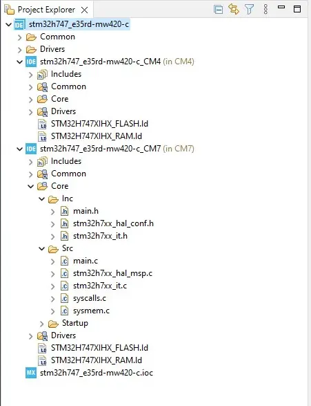
The E35RD-MW420-C Firmware Project
This application note will present the hardware and walk through developing the firmware required
to drive the E35RD-MW420-C MIPI TFT Display with an STM32H747I-DISCO microcontroller board from ST Microelectronics. Driving a MIPI DSI display with a microcontroller presents a few challenges. The STM32H747 has the required bandwidth and I/O pins but lacks enough internal SRAM for a full frame buffer. The DISCO board presented has an external SDRAM chip used for implementing the display frame buffer.
Previous application notes (FAN4221, FAN4222 and FAN4223) had discussed the hardware required, an overview of the firmware, and how to modify the firmware from the E43RB1-FW405-C MIPI TFT Display for the E50RA-I-MW490-C MIPI TFT Display. FAN4224 develops the firmware for the E35RD-MW420-C while reusing the source files common to the MIPI displays.
Introduction
Developing the firmware for the E35RD-MW420-C MIPI TFT Display will be made simpler by reusing
the source files for the E43GB-I-FW405-C (provided by Focus LCDs upon request) and making similar modifications as presented in FAN4223. Like the previous application notes, it is assumed that an adapter PCB will be used to connect the display to the development board. Again, the adapter PCB can be designed by the end user, or the Focus LCDs prototyping adapter board can be used for the project.
Contact Focus LCDs for more information on the Adapter Board and firmware.
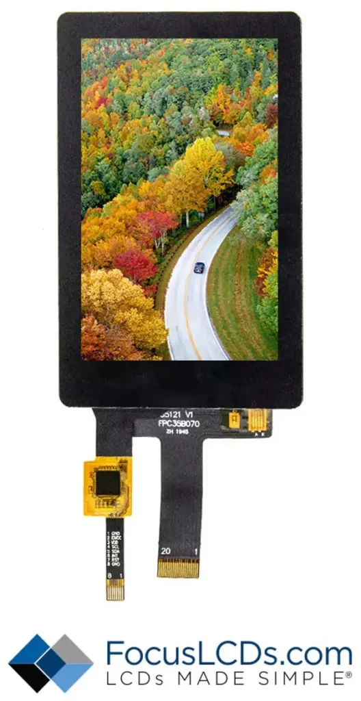
The main features of the E35RD-MW420-C are:
- 3.5” diagonal display, 480 x 800 RGB pixel resolution
- Up to 65k/262k/16.7M (24-bit) color
- 2-Lane MIPI DSI interface with 20 pin FPC cable
- Transmissive/Normally Black display mode
- White LED Backlight
- ST7701S Display Controller
- Capacitive Touch Panel (FT5436) – Touch Mode: 5-Point and Gestures
- Typical Operating Voltage: 3.3V
Hardware Requirements
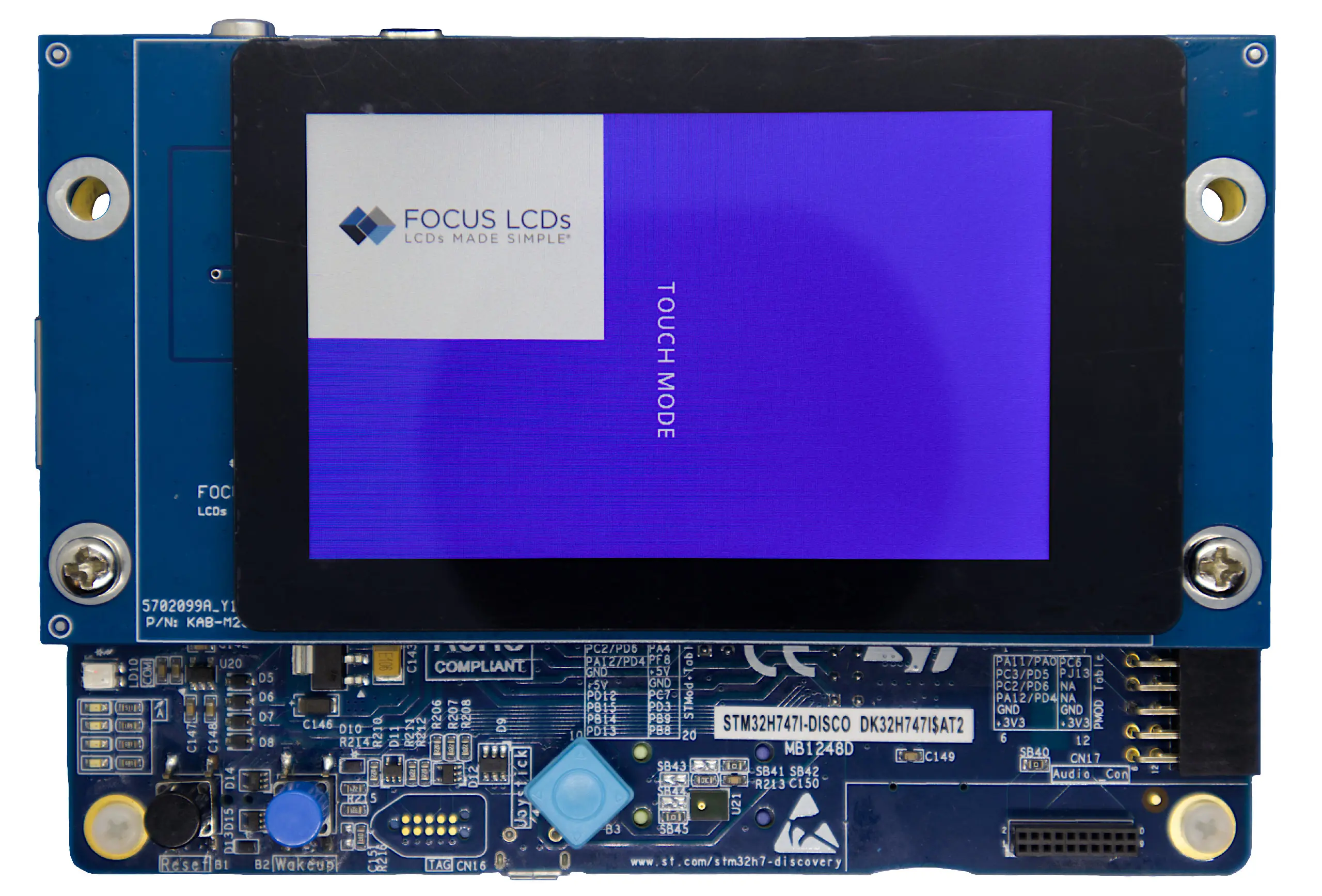
The development board that will drive the display is an STM32H747I-DISCO Discovery Kit. The Kit comes with its own display but for this app note, the stock display will be replaced with the E35RD-MW420-C. See FAN4221 for more information.
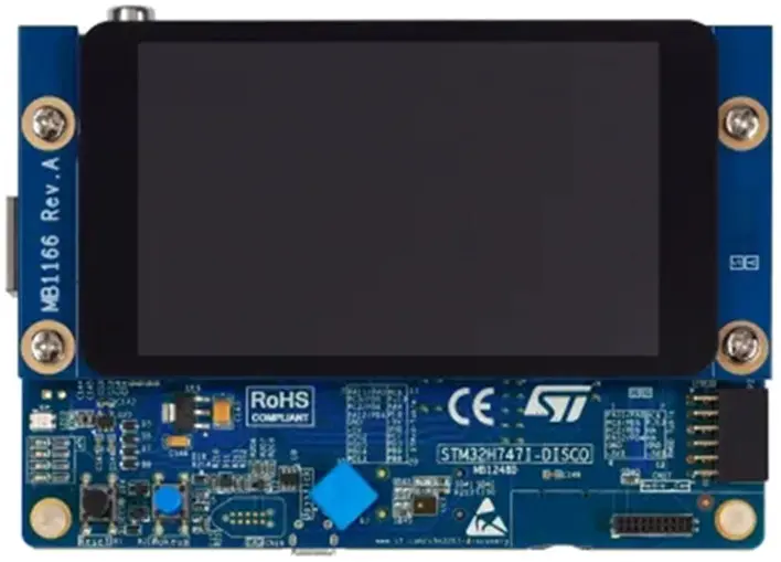
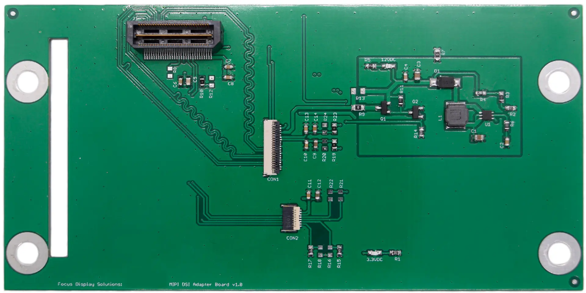
In this application, the Focus LCDs MIPI DSI Adapter Board v1.0 is used to adapt from the Q Strip connector to an FFC connector on the PCB. This adapter board is still in development. Contact Focus LCDs for more information.
Development Tools
STM32CubeIDE
Developing applications typically will use STM32CubeMX for setting up peripheral initialization and STM32CubeIDE (integrated development environment) to code the application side. These tools can be downloaded from the ST website. In this application, only the STM32CubeIDE will be used in the development of the firmware.
After installation, STM32CubeIDE might request additional downloads depending on the device series integrated into the project. When developing the firmware, an additional download for the H7 series of devices was required.
Project Development
In this section, the initial project generation will be presented. The steps to create a new project, what files are to be added, initial modifications, and test building the firmware will be shown.
Start New Project
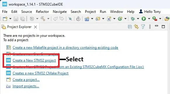
Open STM32CubeIDE and select “Create a New STM32 Project” from the available selections.
The IDE will perform a short download, then open the product selection window.
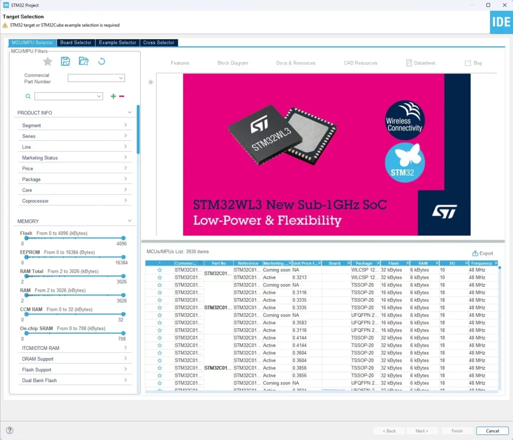
Select the MCU
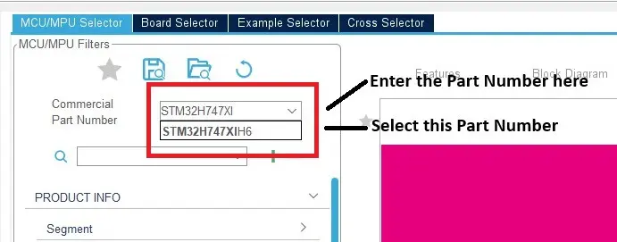
In the “Target Selection” window, look for the box labeled “Commercial Part Number”. This is where the part number of the MCU on the STM32H747I-DISCO will be entered. Enter “STM32H747XI” and select the presented device.
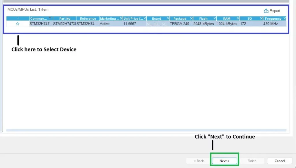
Once the MCU has been selected then click on the device in the “Features” section as outlined in blue.
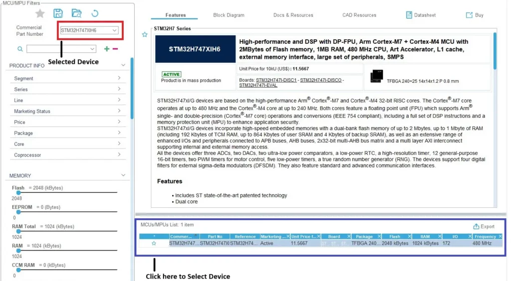
Then click “Next” as highlighted in green.
Name the Project
There are several steps left to finish the project creation. Naming the project is the next step. Keep the default settings as shown in the image below.
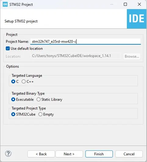
After naming the project, select “Next” to verify the included libraries.
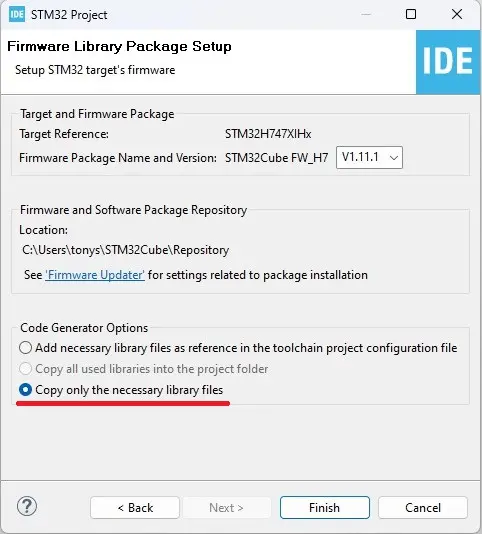
Verify that only the necessary libraries are included.
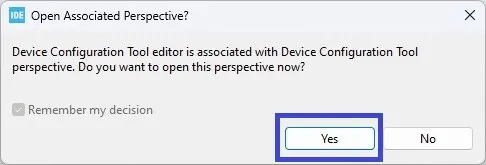
The next two pop up dialogs have optional selections. In both cases, “Yes” was selected. The first is whether the Pinout Configuration Perspective is opened after project generation is completed. “No” can be selected with no effect on the code base.
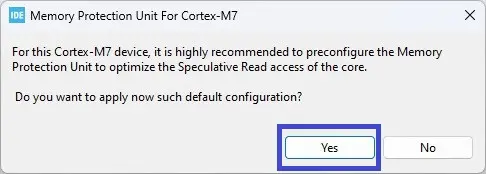
The second pop up dialog will influence code generation. The dialog asks if it should enable the Memory Protection Unit (MPU) to optimize the Speculative Read access of the M7 core. This will add code for configuring the registers involved with the MPU and Speculative Read. This is a minor amount of code and should not affect the operation of the display. Again, selecting “No” is a viable option but in the case of this application note “Yes” was selected and the resulting code compiled into the firmware.
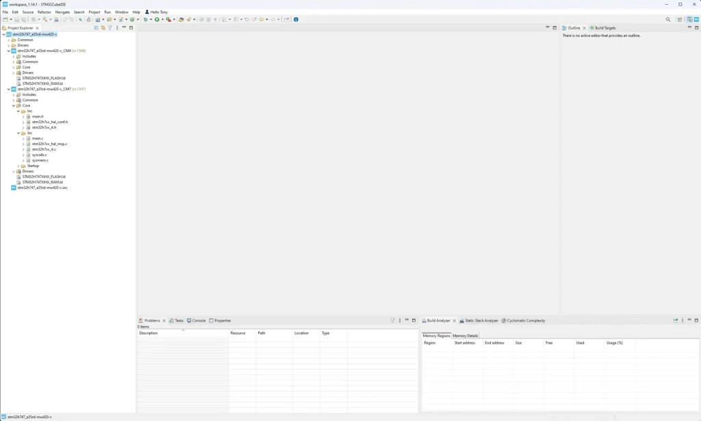
Once those steps are completed the STM32CubeIDE will display:
Add the Files to the Project
The Pinout Configuration perspective can be closed, and the C/C++ perspective opened.
The next step in the creation of the project is to add in the header and source files provided by Focus LCDs and read FAN4222 and FAN4223. Many of the files used throughout these projects are the same. The only difference is the few files based on the differences in the display initialization and timing. Those modifications will be presented in the section: Creating the Firmware Files for the E35RD-MW420-C.
The complete project files for the E35RD-MW420-C, requiring no modification, can be provided by Focus LCDs upon request. This application note is meant as a guide to developing firmware for a display without completed project files.
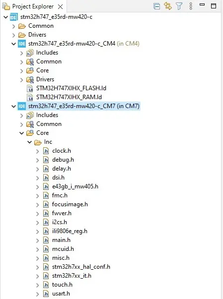
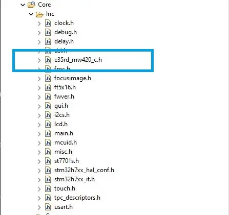
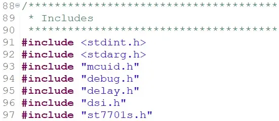
First, add the include files to the project by first opening the development environment workspace and navigating to the CM7 Inc folder. As an example: …/stm32h747_e35rd-mw420-c/CM7/core/Inc. There will be 3 initial files, generated by the tools, in the folder.
Below is the list of header files to copy into the workspace Inc folder.
| clock.h | debug.h | delay.h | dsi.h |
| fmc.h | focusimage.h | ft5x16.h | fwver.h |
| gui.h | i2cs.h | lcd.h | mcuid.h |
| misc.h | touch.h | tpc_descriptors.h | usart.h |
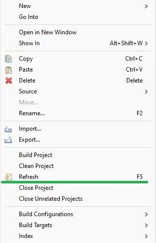
Once the files are copied over to the proper workspace folder location, Project Explorer in the IDE will need to be refreshed to import the added files.
Right click on: stm32h747_e35rd-mw420-c_CM7 to bring up the menu and select refresh. Once the refresh has been completed the newly added files will be part of the project.
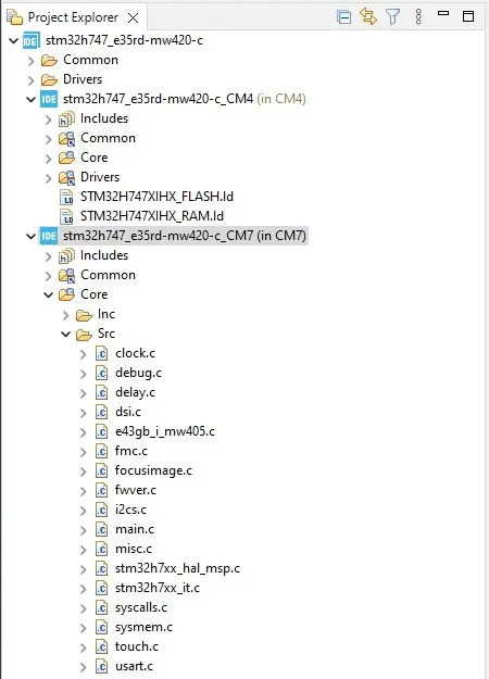
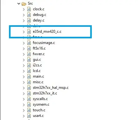
The same procedure will be used to add the necessary files to the source folder. The files will be placed in …/workspace_1.14.1/stm32h747_e35rd-mw420-c/CM7/core/Src. There are 5 files, generated by the dev tool, already in that folder. The files that will be added are:
| clock.c | debug.c | delay.c | dsi.c |
| fmc.c | focusimage.c | ft5x16.c | fwver.c |
| gui.c | i2cs.c | lcd.c | misc.c |
| touch.h | usart.c |
Again, the project will need to be refreshed. Right click on: stm32h747_e35rd-mw420-c_CM7 to bring up the menu and select refresh. Once the refresh has been completed the newly added files will be part of the project as shown below:
Modify main.h and main.c
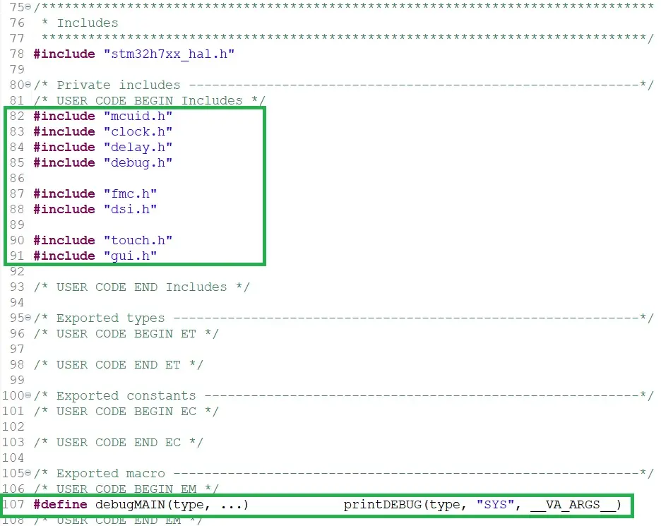
The header files must be included into the main.h file so that the resulting code can be compiled into the firmware. Insert the header files in the code section marked by: /* USER CODE BEGIN Include */. The debug macro can be placed in the section marked by: /* USER CODE BEGIN EM */. Modifications to main.h are shown in the image below:
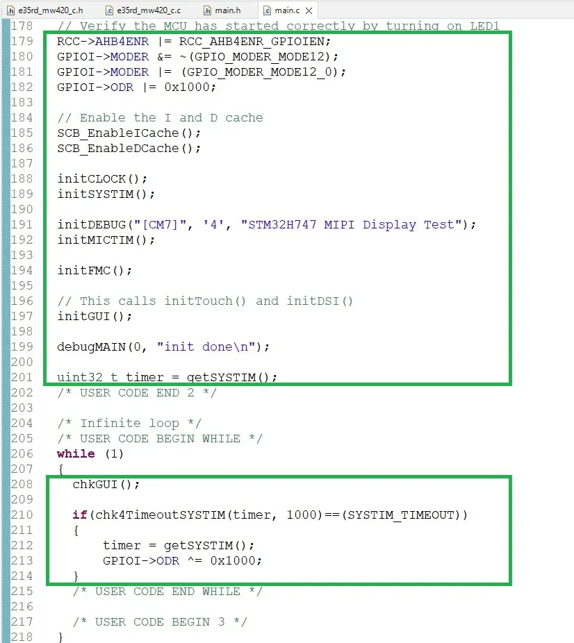
Next, main.c will require some additions for the application code. Looking at the image below, in the first green boxed area, the peripheral and subsystem initialization functions were added under the section: /* USER CODE BEGIN 2 */. The first few lines of code enable User LED1 on the STM32H747 Discovery board. LED1 will blink at a 1Hz rate.
In the same section the macro initDEBUG() and debugMAIN() are added to allow debug messages to be sent over the USART (Universal Synchronous/Asynchronous Receiver Transmitter).
Finally, the chkGUI() function is called in the while(1) loop to respond to touch events. The chk4TimeoutSYSTIM() is used to create a 1 Hz timeout so that use LED1 can be blinked once a second. This verifies the application is running.
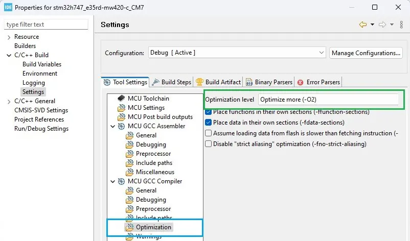
Change Optimization Settings
The next step in creating the firmware is setting the optimization level. The typical setting is ‘-O2’ for a good compromise between execution speed and code size. If left at ‘-O0’ there would be no optimization for execution speed and code size.
First, in Project Explorer right click on the (CM7) project and select properties.
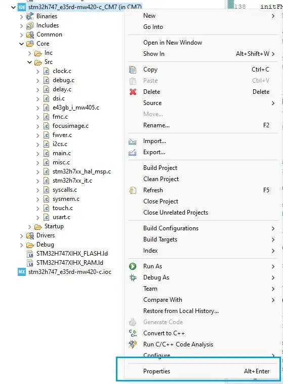
In the pop-up window, select C/C++ Build->Settings.
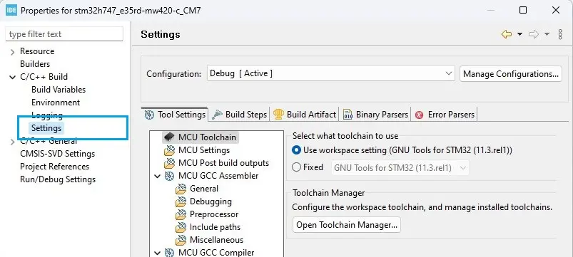
Then in the Tool Settings tab on the right, select Optimization and set the Optimization level to -O2.
Build the Project
The final step to setting up the project is to build the project. This step ensures that there are no missing dependencies. If there are any errors or warnings, resolve those issues before continuing with the firmware project.
Creating the Firmware Files for the E35RD-MW420-C
Using the E43GB-I-MW405-C firmware files as a reference, the E35RD-MW420-C display will be discussed in this section. This will guide the end user through the necessary steps of creating the firmware for the display.
These are the basic steps to creating the firmware:
- Create the display specific files – e35rd_mw420_.c/.h.
- Edit the header file with the inclusion guard, include headers, and API.
- Create the display controller header file – st7701s.h.
- Edit the header file to add the #define for the ST7701S registers.
- Edit the e35rd_mw420_c.c file with the #include header file names.
- Check the LCD controller chip datasheet, the Focus LCDs initialization code, and continue to modify the source file as necessary.
- Edit the .c file with the new display parameters.
- Make the initialization sequence changes of the .c file in runInitSeqLCDConfig() function.
These steps will be discussed in the following sections.
Create the E35RD-MW420-C Header and Source Files
Using the e43gb_i_mw405_c.h and .c files as examples, create a new header file in the Inc folder and a new source file in the Src folder. Name the files e35rd_mw420_c.h and e35rd_mw420_c.c. Once that is completed, code will be added to the new header file.
Editing the Header File
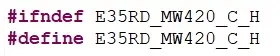
In the header file, verify that the #ifndef __E35RD_MW420_C_H__ matches the new header file name.
Add the include preprocessor commands for the standard C library headers and for the project headers. The <stdarg> header is needed for the __VA__ARGS__ used in the debug code inside the source file.
At this point defines could be added for the LCD width and height in pixels to help make the code more portable between displays. Once that is complete the function prototypes for the API can be placed in the file.
Create and Edit the ST7701S Header File
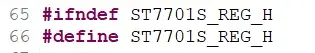
In the header file, verify that the #ifndef ST7701S_REG_H matches the new header file name.
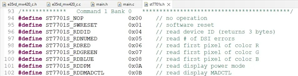
Looking at the ST7701S datasheet, the section on the commands/registers is what will populate the header file. Start by #define the commands and data bytes for changing register pages.
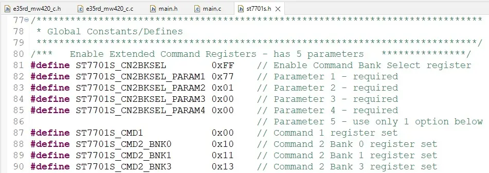
Next, add the rest of the command registers to the header file.
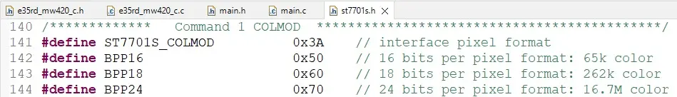
Some command registers have named bit fields. Define these bit names so they can later be used to configure their associated register. See the COLMOD register and bit defines below for an example.
Complete all the register and bit defines for the ST7701S.
Editing the Source File
First, looking at the datasheet for the E35RD-MW420-C, notice the TFT controller chip is the ST7701S.
In the e35rd_mw420_c.c source file, the #include directives must be added for E35RD-MW420-C and the ST7701S. The header file include should be #include “e35rd_mw420_c.h” and #include “st7701s”.
The debugging system requires a constant module name and a macro that provides an alias to the function pointer for printing debug messages.

Setting up Arrays for the Command Parameters
Many of the commands for controlling the initialization of the display have associated parameters. One of the first items to code are the arrays with the data for the commands as the DSI packet write functions (provided by the ST include and source files generated with project creation) require arrays when there is more than 1 byte of data for a command.
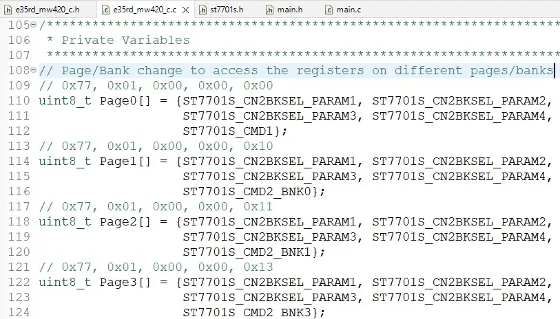
Different display controllers have command sequences to access additional register pages or banks.
Initial Parameter Configuration
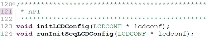
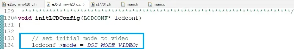
The parameters of the TFT LCD will be set and initialized in the void initLCDConfig(LCDCONF *lcdconfig) function in the e35rd_mw420_c.c file. The argument LCDCONF is a structure containing all the essential information required by the DSI controller to configure the MIPI DSI interface.
Command or Video Mode and Additional Configuration
Identifying whether the display operates in MIPI video or command mode can be verified by reviewing the controller datasheet for GRAM. If the controller has GRAM, it can operate in command mode but if there is no GRAM it must operate in video mode. Reviewing the ST7701S datasheet shows that it has no internal GRAM and operates in video mode. In the source file the mode is set to DSI_VIDEO_MODE and does not need to be changed as both displays use the same controller.
Looking at the datasheet, the display resolution is 480 x 800. Modify the configuration height and width. The LCD_WIDTH and LCD_HEIGHT are defined in the e35rd_mw420_c.h file.
The next set of parameters to consider are the display timings. These can sometimes be found in the display datasheet or from the comments section of the display initialization file. Both can be found on the Focus LCDs website or are available upon request. Carry the over the display timings to the LCDCONF structure.
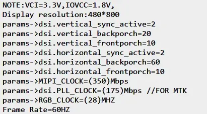
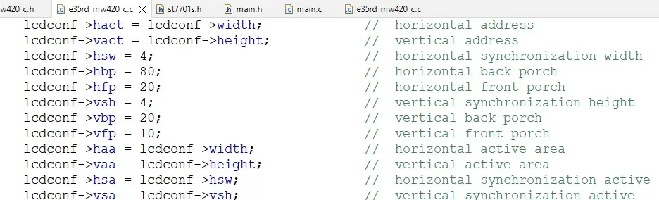
Due to slight variations in timing, some parameters may need to be adjusted to ensure proper functioning of the display.
Configuring the Initialization Sequence
Having adjusted the timings for the display, the initialization sequence will be modified for the new display. In the previous section, the display timings were retrieved from the display initialization file. The commands for display initialization are included in that file.
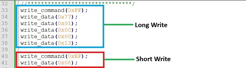
There are two types of writes, command and data. The write_command() is the address of the register where the data will be written. The write_data() is the data that will be written to the register.
Commands that take more than 1 parameter require the use of the long write function, example using the above command longWriteDSI(lcdconf->virch, long_pkt_write_type, 5, 0xFF, Page3). Commands that require 1 or no data parameters are call short write functions like shortWriteDSI(lcdconf->virch, short_pkt_write_type, 0xEF, 0x08). In the initialization code when a command has no corresponding data then a short write is used with the last parameter being set to 0x00.
The display initialization code is generic ‘C’ code to show the concept of registers and data to be placed in those registers. This is where the MIPI DSI concepts of short and long write packets are used for data transfer. The end user needs to convert the display initialization code into short and long DSI packet writes. The function used for calling all the initialization code is:
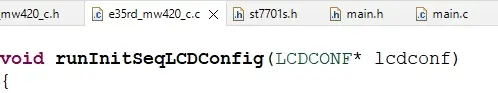
Continue to edit the void runInitSeqLCDConfig(LCDCONF *lcdconf) function. This is required for all the write commands and associated data in the display initialization file. Shown below is a section of the additions to runInitSeqLCDConfig() function.
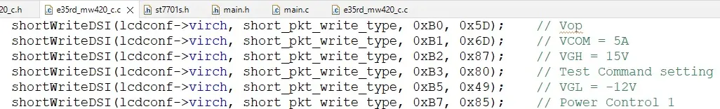
Figure 44: A Sample of the runInitSeqLCDConfig()
Function
In the figure above, the shortWriteDSI() functions are used to send commands to the display. The short packet functions are used when a command with no data or 1 data parameter needs to be transmitted to the display. Long packet writes are used when there is more than 1 data parameter to transmit.
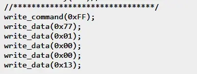
Looking at the display initialization code, there are 5 parameters to the page change command. In the figure below, an example of a long write packet is the DSI version of the page change command. The last parameter, Page3, is the array which stores the 5 parameters.

The commands that have several data parameters should have arrays for the data parameters to be passed to the longWriteDSI() function. Some of these commands include the Positive and Negative Gamma settings and the GIP settings. Once all the changes have been made to the various headers and source files, the demo will build and can be downloaded onto the STM32H7 Discovery board with the appropriate display attached.
Additional Comments
The source code with the modifications already completed with the addition of the required code for driving the touch panel can be provided by Focus LCDs upon request.
Summary
In Part 1, the hardware requirements for a MIPI display demo were presented. How to assemble the hardware was shown. Finally, a brief overview of the MIPI DSI interface and the STM32 DSI Host peripheral were discussed.
In Part 2, it was shown how to modify the code for a similar display, the E50RA-I-MW490-C display.
In Part 3 presented here, the sections went through the operation of modifying the firmware for the E35RD-MW420-C display. Through the modification of the firmware, the structure and basic layout of the code is shown.
LCD Handling Precautions
- Do not store the TFT-LCD module in direct sunlight, best stored in a dark place.
- Do not leave it exposed to high temperature and high humidity for a long period of time.
- Recommended temperature range is 0 to 35 °C, relative humidity should be less than 70%.
- Stored modules away from condensation as formation of dewdrops may cause an abnormal operation or failure of the module.
- Protect the module from static discharge.
- Do not press or scratch the surface and protect it from physical shock or any force.
Disclaimer
Buyers and others who are developing systems that incorporate FocusLCDs products (collectively, “Designers”) understand and agree that Designers remain responsible for using their independent analysis, evaluation, and judgment in designing their applications and that Designers have full and exclusive responsibility to assure the safety of Designers’ applications and compliance of their applications (and of all FocusLCDs products used in or for Designers’ applications) with all applicable regulations, laws, and other applicable requirements.
Designer represents that, with respect to their applications, Designer has all the necessary expertise to create and implement safeguards that:
(1) anticipate dangerous consequences of failures
(2) monitor failures and their consequences, and
(3) lessen the likelihood of failures that might cause harm and take appropriate actions.
The designer agrees that prior to using or distributing any applications that include FocusLCDs products, the Designer will thoroughly test such applications and the functionality of such FocusLCDs products as used in such applications.