Working with the E43RB1-FW405-C MIPI Display (Part 2)
This series of application notes will discuss the hardware and software requirements of driving the E43RB1-FW405-C MIPI DSI TFT Display with an STM32H747I-DISCO microcontroller board from ST Microelectronics. Driving a MIPI DSI display with a microcontroller presents a few challenges. The STM32H747 has the required bandwidth and I/O pins but lacks enough internal SRAM for a full frame buffer. The DISCO board presented has an external SDRAM chip used for implementing the display frame buffer.
Previously, Part 1 (FAN4221) walked through the hardware requirements and interfacing the display. Part 2 (FAN4222) will present a high-level overview of the firmware and project structure. In Part 3 of the series (FAN4223), modifications to the firmware will be made to support the E50RA-I-MW490-C TFT MIPI display.

Introduction
The aim of this document is the continuation of the application note started in FAN4221 where the hardware aspects of this project were discussed. Part 1 presented the hardware requirements and Part 2 will focus on the software implementation and configuration. This process will show how the Development Tools were used for initial configuration. Later, it will be shown how to modify the code to suit other Focus LCDs MIPI displays with 20-pin FPC cables.
The code will demonstrate the capabilities of the E43RB1-FW405-C display. A demonstration application was implemented which includes different background colors and an image depending on where the user touches the display. In addition to showing the display initialization (mainly the MIPI DSI peripherals) this application note is intended to show the performance of the Capacitive Touch Panel (CTP).
It is expected that the E43RB1-FW405-C MIPI Display will be connected to the Adapter Board and plugged into the STM32H747I-DISCO Development Board. Contact Focus LCDs for more information on the Adapter Board.
Development Tools
STM32CubeMX
Developing applications typically will use STM32CubeMX for setting up peripheral initialization and STM32CubeIDE (integrated development environment) to code the application side. These tools can be downloaded from the ST website. The first time setting up a project in STM32CubeMX will force a download of additional software components.

Manipulating the pin and peripheral configuration in STM32CubeMX is easy to perform. However, using the STM32CubeMX SDK adds overhead to the code structure as well as the microcontroller (MCU). In complex projects the overhead can affect the performance of the MCU. In this application, STM32CubeMX was not used in the development of the firmware.
STM32CubeIDE
After installation, STM32CubeIDE might request additional downloads depending on the device series integrated into the project. When developing the firmware, an additional download for the H7 series of devices was required.
Frame Buffer Considerations
The STM32H747I-DISCO MCU Board has an STM32H747 MCU which is a dual core Cortex M7 + Cortex M4 with 2 MB of non-volatile memory (flash memory) and 1 MB of volatile memory SRAM. The SRAM is allocated into a few non-consecutive address regions:
- 128 kB of tightly coupled memory for data (DTCM)
- 64 kB of tightly coupled memory for instructions (ITCM)
- 4 kB backup SRAM
- 16 kB shared memory for communication between the M4 and M7 cores
- 512 kB AXI SRAM
- 256 kB SRAM
The example application code was written for M7 core while the M4 core is not utilized.
Higher resolution displays do not typically come with internal graphics RAM (GRAM) that can be used for the frame buffer. The system the display is attached to is required to provide a buffer for the display. These displays operate from real-time pixel streams transferred from the host processor. This requires the host processor to have sufficient bandwidth and memory to avoid flickering and other visible artifacts in the displayed image.
It is advisable to select an MCU with a large internal SRAM or internal dynamic RAM (DRAM) to contain the full frame buffer. The fact is most MCUs on the market do not have enough internal SRAM. In many situations the frame buffer will have to be stored in an external memory necessitating an external memory controller.
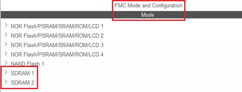
The STM32 family of MCUs has a range of devices with flexible memory controllers (FMC). An external SDRAM tied to the external memory bus can be used for the allocation of the frame buffer. The issue to note is external SDRAM can be 3x to 4x (best case) slower than the internal SRAM.
Frame buffer memory requirements are defined by the resolution of the display and the color bit depth. It can be calculated as follows: resolution width (in pixels) x resolution height (in lines) x internal color representation (color bit depth)/8 (bits per byte). The E43RB1-FW405-C has a resolution of 480 x 800 and can display 24-bit color. The MCU represents that color depth internally as 32-bit ARGB (A for the alpha channel). This equates to 1,536,000 bytes or 1.5 MB. This will not fit in the internal SRAM of the MCU. The external SDRAM chip has 512 Mbits of memory or 64 MB and is more than sufficient to contain several buffers.
Demonstration of Firmware
The demo application shows the possible functionality of the display and touch panel. The display’s background color can be changed (red, green, or blue) by touching the indicated areas shown in the image below. The Focus LCDs logo can be hidden or shown, again by touching the indicated area of the display. In the image below, the initial state is displayed with the logo shown over a red background.
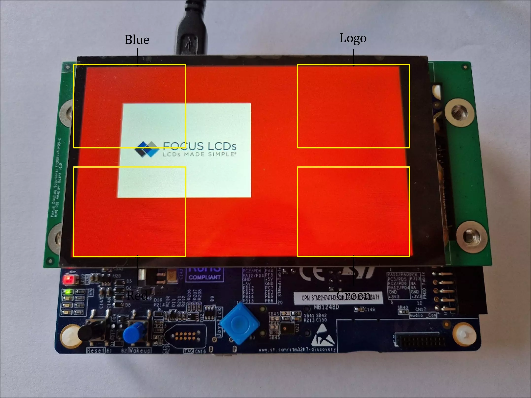
The marked areas in the image represent the touch event locations and change the display accordingly. As an example, touching the area for the “Blue” color will change the background color to blue and erase any prior content. To add the logo to the display, the user can touch the area marked “Logo”. Touching the area marked “Blue” again will remove the logo but retain the blue colored background. This can be changed with the other colors by touching the appropriate areas.
The solid color and the logo are written to the frame buffer (in SDRAM) prior to being displayed. Next, the LTDC (LCD-TFT Display Controller) reads the data from the buffer and formats it into and RGB888 video stream and sends it to the DSI peripheral. Finally, the DSI Host (Display Serial Interface) converts the video data into a 2-Lane, differential pair signal stream for MIPI displays.
To display more than static images (examples include video or animation) it is recommended that at minimum a double buffer system be implemented. This allows for one image to be written to a buffer while a completed image can be read into the LTDC. This will reduce the screen tearing seen in the demo when changing the color or logo. It is beyond the scope of this document to show how to implement a double buffer system.
The firmware can be provided by Focus LCDs upon request.
Project Structure and Firmware
In this section the demonstration firmware will be presented. This is a high-level overview of the firmware and the different functionalities. After creating a new STM32 project in the STM32CubeIDE, several folders are generated by the tool. The “Common” and “Drivers” folders contain the STM32 HAL and CMSIS which contain the Cortex core and peripheral header files. In addition, the CM4 core files are included in the project. None of these files are modified from their original generation by the IDE.
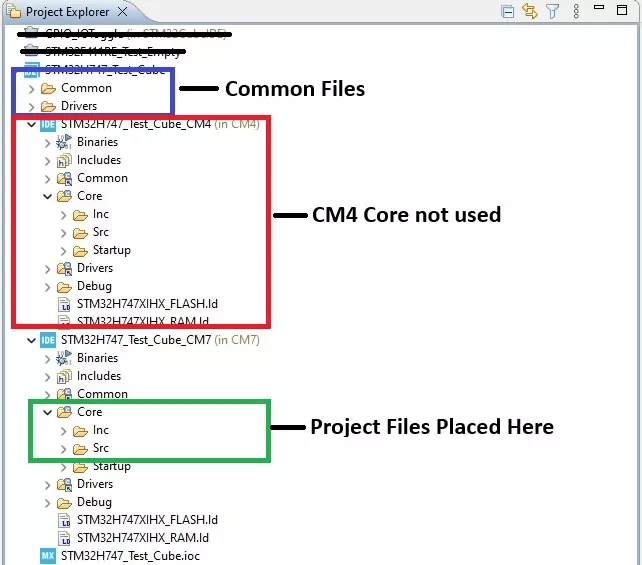
As shown above, the common files (outlined in blue) and the CM4 core files (outlined in red) are generated for the project. These do not get modified. Outlined in green are the core files for the CM7. These are the folders where the demonstration header and source files were added to the project. Along with the file additions, the main function was modified for the demo.
Project Structure
- Common – this contains the dual core (CM4 and CM7) boot source file.
- Drivers – holds the folders for the CMSIS and STM32 HAL drivers.
- CMSIS – these are the ARM provided files for the core MCU and ARM peripherals.
- STM32 HAL – these are the files provided by ST Microelectronics for their peripherals.
- Binaries (CM4 and CM7) – this is where the output binary files are located (.bin, .elf, and .hex).
- Includes (CM4 and CM7) – these are the folders for additional include files common to all STM32 projects.
- Common (CM4 and CM7) – this is just a symbolic link to the “Common” folder higher in the project structure.
- Core (CM4 and CM7) – this is where the demonstration firmware is located.
- Inc – contains main.h and the user generated include files for the project.
- Src – contains main.c and the user generated source files for the project.
- Startup – this has the assembly startup file for the MCU cores.
- Drivers (CM4 and CM7) – this is just a symbolic link to the “Drivers” folder higher in the project structure.
- Debug CM4 and CM7) – this folder has the “debug” versions of the object files generated in the build process.
- Release – (Not Shown) – this folder has the “release” versions of the object files generated in the build process.
- The last 2 files shown are the linker scripts for the memory location and layout used in the build process.
Firmware Overview
The firmware developed for the demonstration is outlined in this section. Files generated or included by the development environment will not be discussed. An overview of the files added to or modified for the project will be presented below.
The major functions of the firmware are separated out by the peripheral or subsystem. A short description of each peripheral or subsystem is discussed. Finally, the functions of each subsection are given a short explanation.
The demonstration project for M7 core includes following files:
- clock.c – implements the code related to the clock system setup so that CPU and other peripherals are running at their nominal frequencies (M7: CPU at 480MHz, M4: CPU at 240MHz)
- void initClock(void) – initializes clock on the MCU ensuring that clock sources, PLLs and clock dividers are properly configured.
- clock.h – function declaration for clock.c functions.
- debug.c – an advance debugging system with a coloring scheme implementing printf-like functionality with the addition of the calling peripheral and timestamp in milliseconds.
- void initDebug(char * cpuName, uint8_t color, char * appName) – initializes debug interface with proper initialization of an UART. Writes out basic firmware information.
- void NMI_Handler(void) – handles critical system problems. NMI (non-maskable interrupt) is a hardware interrupt that standard interrupt masking techniques cannot ignore.
- void HardFault_Handler(void) – handles hard errors and writes out the whole register set values when the hardfault was triggered. Uses inline assembly for handling. Jumps to HardFault_HandlerC
- void HardFault_HandlerC(void) – handles hard faults using C code and prints register values. Enters an infinite loop after completion.
- void MemManage_Handler(void) – handles memory management faults (accessing restricted memory). Halts the system upon completion.
- void BusFault_Handler(void) – handles bus faults (invalid memory access). Halts the system upon completion.
- void UsageFault_Handler(void) – handles usage faults (undefined instruction). Halts the system upon completion.
- debug.h – function declaration for debug.c functions.
- delay.c – implements blocking (delay ms and us) and nonblocking (ms granularity) time functions.
- void delay_ms(uint32_t ms) – executes the delay value given in milliseconds.
- void delay_us(uint32_t us) – executes the delay value given in microseconds.
- void initSYSTIM(void) – initiates system timer with TIM5.
- uint32_t getSYSTIM(void) – returns the current time, the value stored in the CNT register of TIM5. Returns time in milliseconds.
- uint8_t chk4TimeoutSYSTIM(uint32_t btime, uint32_t period) – calculates if a given period has elapsed based on given btime.
- uint32_t getElapsedTimeSYSTIM(uint32_t t_beg) – measures time elapsed from a given time point (t_beg).
- void initMICTIM(void) – initiates a microsecond timer using TIM4.
- void begMICTIM(void) – starts the TIM4 by clearing flags, resetting count, and enabling the timer.
- uint32_t getMICTIM(void) – returns the current time, the value stored in the CNT register of TIM4. Returns time in microseconds.
- delay.h – function declaration for delay.c functions.
- dsi.c – provides the functions for an interface to communicate with a DSI-compliant display. Communicates with the internal LTDC peripheral. These are the functions that control and stream the image to the MIPI display.
- void initDSI(void) – initializes DSI host interface with proper configuration of the LTDC peripheral, configures video mode, powers on the display, and loads default image.
- void DSI_IRQHandler(void) – manages interrupt events from the DSI controller.
- void readRegsDSI(void) – reads display configuration from the contents of the registers.
- void readPageRegDSI(uint8_t * page, uint8_t reg, char * name) – reads the display configuration registers depending on the page where the register is located.
- uint8_t shortWriteDSI(uint32_t channelID, uint32_t mode, uint32_t param1, uint32_t param2) – writes 2 parameters out of the DSI peripheral to the display. Typically, a command and data pair.
- uint8_t longWriteDSI(uint32_t channelID, uint32_t mode, uint32_t numParams, uint32_t Param1, uint8_t * parameterTable) – writes several parameters to the display. Typically, a command that has several data to write. The data is stored in an array. This is also the routine that writes the image data to the display.
- uint8_t readRegDSI(uint32_t channelID, uint32_t mode, uint16_t reg, uint8_t * data, uint8_t size) – prepares a read command with the register address then calls readDSI.
- uint8_t readDSI(uint32_t channelNum, uint8_t * array, uint32_t size, uint32_t mode, uint32_t DCSCmd, uint8_t * parameterTable) – reads data from the DSI controller depending on the mode.
- void cfgPktHeaderDSI(uint32_t channelID, uint32_t dataType, uint32_t data0, uint32_t data1) – Updates the DSI packet header with new information.
- void fillScreenDSI(uint32_t color) – fills the display screen with the given color and refreshes the display. The color is in ARGB8888 format.
- void loadImageDSI(void) – loads the display screen with a predetermined image. In the case of the demo, the Focus LCDs logo is displayed.
- dsi.h – function declaration for dsi.c functions.
- fmc.c – flexile memory controller (FMC) for frame buffering and accessing the SDRAM (bank 2).
- void initFMC(void) – initializes the FMC for communication with the external SDRAM.
- uint8_t sendCmdFMC(uint32_t mode, uint32_t target, uint32_t autoRefreshNum, uint32_t modeRegisterDefinition, uint32_t timeout) – prepares the command and uses the FMC to send it to the SDRAM.
- void unitTestSDRAM(uint32_t address, uint32_t sdramSize, uint8_t dsize, uint32_t testCount, uint32_t testDelay) – tests out the SDRAM by writing and reading from it.
- fmc.h – function declaration for fmc.c functions.
- focusimage.c – provides the image data, as an array, to display on the screen.
- typedef struct {} image_t;
- focusimage.h – structure definition for image data.
- i2cs.c – implements the I2C protocol to communicate with external peripherals.
- void initI2C(void) – configures GPIO and initializes an I2C slave interface.
- void deinitI2C(I2C_DESC * I2C) – resets GPIO and deinitializes the I2C interface.
- uint8_t scanI2C(I2C_DESC * I2C, uint8_t address) – scans for active slaves and returns the number of devices found.
- uint8_t chkAddrI2C(I2C_DESC * I2C) – verifies if a slave is active.
- uint8_t readI2C(I2C_DESC * I2C, uint32_t reg, uint8_t * data, uint16_t numBytes) – reads data from the I2C slave.
- uint8_t writeI2C(I2C_DESC * I2C, uint32_t reg, uint8_t * data, uint16_t numBytes) – writes data to the I2C slave.
- void startI2C(I2C_DESC * I2C) – starts the I2C communication by configuring SDA and SCK pins.
- void stopI2C(I2C_DESC * I2C) – stops the I2C communication by configuring SDA and SCK pins.
- void writeByteI2C(I2C_DESC * I2C, uint8_t data) – called by writeI2C() to write 1 byte at a time out of the I2C port.
- uint8_t readByteI2C(I2C_DESC * I2C) – called by readI2C() to read 1 byte from the I2C port.
- uint8_t ackSlaveI2C(I2C_DESC * I2C) – checks if a slave has sent an ACK.
- void ackMasterI2C(I2C_DESC * I2C) – master sends ACK to slave.
- void nackMasterI2C(I2C_DESC * I2C) – master sends NACK to slave.
- i2cs.h – function declaration for i2cs.c functions.
- ili9806e_reg.h – register header file for the display driver chip.
- main.c – main function file holding core loop running code.
- This file was modified from the generated version for the demo firmware.
- main.h – function declaration for main.c functions.
- touch.c – GT911 driver functions for the touch interface using the I2C peripheral.
- void initTouch(void) – initializes touch interface by setting up GPIO pins, event handlers, and prepares I2C for communication.
- void chkTouch(void) – checks for touch with interrupt and react accordingly. If touch is detected it is serviced depending on location, change color or image based on touch location.
- touch.h – function declaration for touch.c functions.
- usart.c – UART peripheral initialization for the purpose of debugging.
- void initUSART1(uint32_t baudrate) – initializes USART 1 interface and configure PA9 pin as TX and PA10 as RX.
- void putcharUSART1(uint8_t data) – sends a single byte or char of data over the USART interface.
- void printUSART1(char * str, …) – sends an arbitrary number of bytes over the USART interface with printf style formatting.
- void sprintUSART1(uint8_t * str) – sends a null-terminated string over the USART interface 1 character at a time.
- uint8_t getcharUSART1(void) – reads if there is any data received by reading the RDR (Receive Data Register) and returns it.
- usart.h – function declaration for usart.c functions.
- Makefile – the makefile file describing compilation and linking process for the code as well the firmware flashing instructions. This was modified to include the additional files for the project.
Summary
In Part 1, the hardware requirements for a MIPI display demo were presented. How to assemble the hardware was shown. Finally, a brief overview of the MIPI DSI interface and the STM32 DSI Host peripheral were discussed.
In Part 2 presented here, the development tools and frame buffer consideration were briefly discussed. The demonstration firmware operation was mentioned along with the touch interface. Finally, the project structure and firmware overview are shown with specific reference to the E43RB1-FW405-C MIPI Display.
In Part 3, a walk through on how to modify the firmware for the E50RA-I-MW490-C TFT MIPI display will be presented.
LCD Handling Precautions
- Do not store the TFT-LCD module in direct sunlight, best stored in a dark place.
- Do not leave it exposed to high temperature and high humidity for a long period of time.
- Recommended temperature range is 0 to 35 °C, relative humidity should be less than 70%.
- Stored modules away from condensation as formation of dewdrops may cause an abnormal operation or failure of the module.
- Protect the module from static discharge.
- Do not press or scratch the surface and protect it from physical shock or any force.
Disclaimer
Buyers and others who are developing systems that incorporate FocusLCDs products (collectively, “Designers”) understand and agree that Designers remain responsible for using their independent analysis, evaluation, and judgment in designing their applications and that Designers have full and exclusive responsibility to assure the safety of Designers’ applications and compliance of their applications (and of all FocusLCDs products used in or for Designers’ applications) with all applicable regulations, laws, and other applicable requirements.
Designer represents that, with respect to their applications, Designer has all the necessary expertise to create and implement safeguards that:
(1) anticipate dangerous consequences of failures
(2) monitor failures and their consequences, and
(3) lessen the likelihood of failures that might cause harm and take appropriate actions.
The designer agrees that prior to using or distributing any applications that include FocusLCDs products, the Designer will thoroughly test such applications and the functionality of such FocusLCDs products as used in such applications.