Driving a 128×64 Graphic LCD with a Microcontroller: A Programming Guide
Driving a Graphic LCD with a Microcontroller Board
In this application the hardware used, and firmware developed to drive a graphic LCD will be presented. The graphic LCD in this application note is the G126FLGFGS164T33XAR from Focus LCDs. The STM32F411RE-Nucleo from ST Microelectronics will be the microcontroller board for this project. The Firmware will be developed for the Nucleo-F411 board.
Introduction
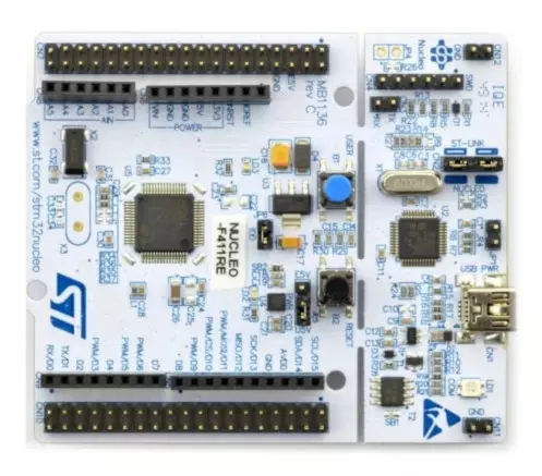
Driving the G126FLGFGS164T33XAR graphic with images will require a microcontroller development board and firmware. The development board chosen for this project is the STM32F411RE-Nucleo. This application note will show the hardware and firmware development with the STM32F411RE-Nucleo. The board has a 3.3V supply rail with enough current to power the LCD and SPI interface. Though not required, a separate 3.3V power supply will power the backlight to ensure the required amount of current is provided.
Contact Focus LCDs for more information on the graphic LCD and firmware.
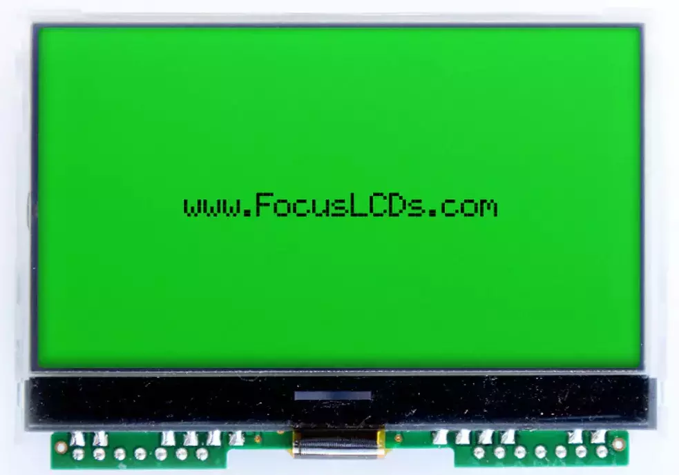
The G126FLGFGS164T33XAR display used in this application is a 3.175” graphic LCD with a 128 x 64 monochrome dot resolution from Focus LCDs. This display is interfaced using the SPI protocol with 14 through hole pins.
The main features of the G126FLGFGS164T33XAR are:
- 3.175” Diagonal Display, 128 x 64 Dot Resolution
- Monochrome color
- SPI interface
- Transflective, FSTN Positive
- RGB LED Backlight
- ST7565P Display Controller
- Typical Operating Voltage: 3.3V
Hardware Requirements
The development board that will drive the display is STM32F411RE-Nucleo board, as shown below.
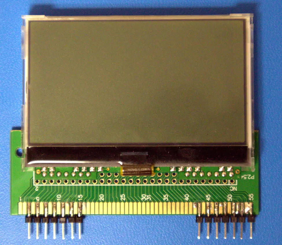
In addition to the development board, a piece of prototyping PCB is used to connect the display to header pins. The display is soldered to the prototype PCB along with the header pins. This allows standard Female-to-Male jumper wires to be connected between the development board and display.
In the table below, the connections from the display and prototype board to the STM32F411RE Nucleo are listed.
| G126FLGFGS164T33XAR Display | STM32F411RE-Nucleo | |||||
| Pin | Signal | Function | Pin | Connector | Port | Signal |
| 2 | SCL | Serial Clock | 25 | CN10 | PB10 | SCK |
| 3 | SI | Serial Data | 37 | CN7 | PC3 | MOSI |
| 4 | VDD | 3.3V Power | 5 | CN7 | – | VDD |
| 5 | A0 | Register Select | 38 | CN7 | PC0 | A0 |
| 6 | /Reset | Reset Signal | 36 | CN7 | PC1 | NRST |
| 7 | /CS | Chip Select | 16 | CN10 | PB12 | NCS |
| 8 | VSS | Ground | 19 | CN7 | – | GND |
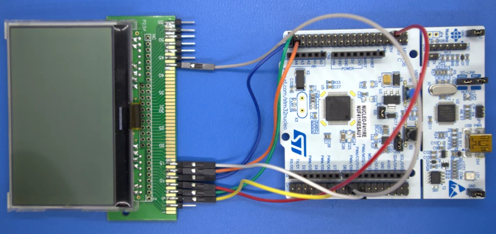
The image below shows the physical connections between the display and board.
Development Tools
STM32CubeMX and STM32CubeIDE
Developing applications will typically use STM32CubeMX for setting up peripheral initialization and STM32CubeIDE (integrated development environment) to code the application side. These tools can be downloaded from the ST website. They do require an account to be created before downloading the tools.
Here is the STM32CubeMX Development Tool:
The STM32CubeMX tool will be used to configure the peripherals that will be used to drive the graphic LCD. In this application, the general-purpose IO and the SPI serial port will be configured. In addition, a USART will be configured in case the end user would like to use a serial port for debugging.
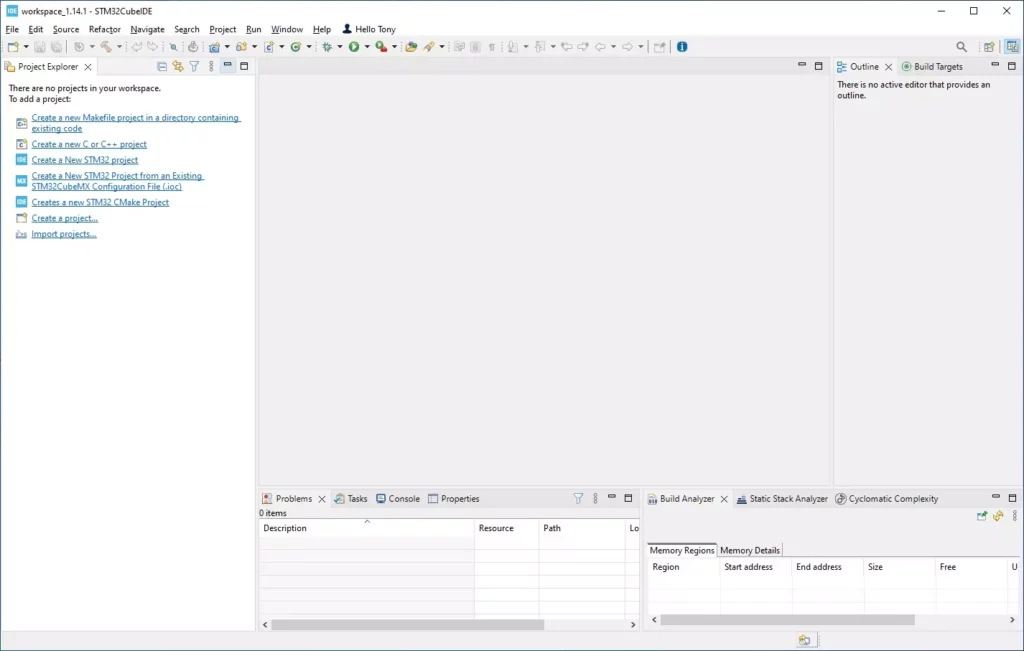
Next is the STM32CubeIDE Development Environment:
After installation, STM32CubeMX or STM32CubeIDE might request additional downloads depending on the device series integrated into the project. When developing the firmware, an additional download for the F4 series of devices was required for both tools.
STM32F411RE-Nucleo Project Development
In this section, the initial project generation will be presented. The steps to create a new project, what files are to be added, initial modifications, building, and testing the firmware will be shown.
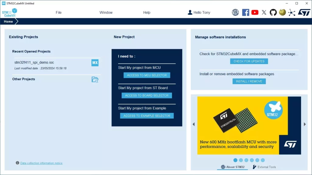
Start a New Project in STM32CubeMX
Open STM32CubeMX and select “Start My project from ST Board” from the available selections under the “New Project”. This will bring up the board selection dialog. In the “Commercial Part Number” drop down, type in “Nucleo-F411RE” This will then show the board in the “Board List” in the lower half of the window. Click on the board image shown and a detailed view of the board will be displayed in the upper half of the window.
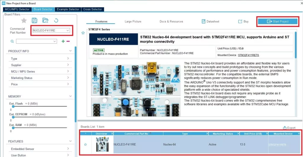
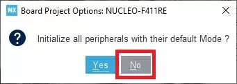
Once the board has been selected, click on “Start Project” and select “No” in the initialize default peripherals dialog.
Peripheral Configuration
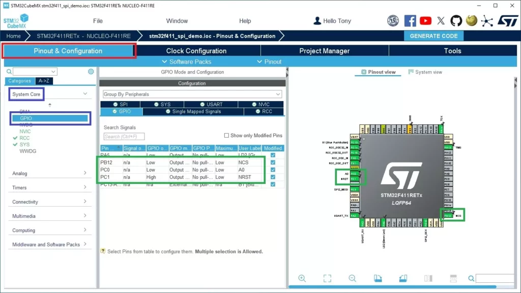
In this section, the peripherals will be configured. Start in the “Pinout & Configuration” tab, and under that select “System Core” to access the GPIO.
In the datasheet for the G126FLGFGS164T33XAR, there are 3 pins that need to be configured to control the display. The A0 pin is the register select pin, which determines if the SPI transfer is a command (LOW) or data (HIGH). A0 will be initialized to idle high to avoid accidentally sending a command. The next pin is RESET (NRST), which is active low. This pin will also be set to idle high to avoid accidental resets. The chip select signal (NCS) will also be configured as a GPIO to have finer control of when it gets activated. NCS is active low and like the other pins, it will idle high. These settings are shown in the image below.
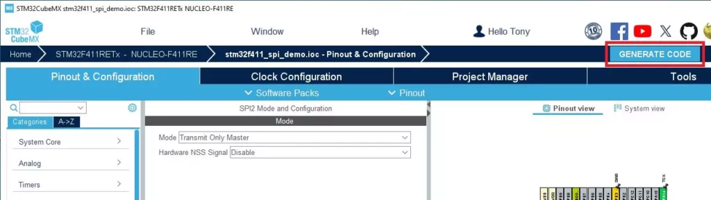
Once the GPIO pins are configured, the SPI peripheral is next. In this application, SPI2 will be used as SPI1 is unavailable. Again, in the “Pinout & Configuration” tab, select the “Connectivity” section to gain access to SPI2 configuration. Under “SPI2 Mode & Configuration” (center section), set the Hardware NSS Signal to disable since a GPIO (NCS) will be used to select the ST7565P display controller. Next, set the basic parameters for Motorola, 8-bits, and MSB first.
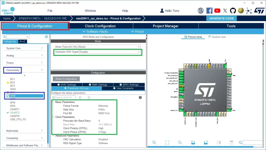
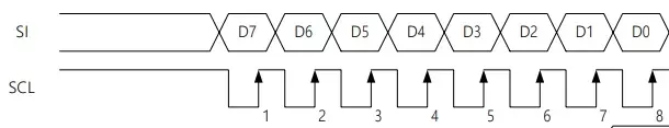
The clock parameters are critical to the correct communication between the display and development board. Set the Baud Rate prescaler to 4 so that the serial clock is within the ST7565P clock limitations. Looking at the ST7565P datasheet for the SPI clock timing diagram, it is shown that the clock idles high, and that the data is read on the second edge. Set Clock Polarity to High and Clock Phase to 2 Edge.
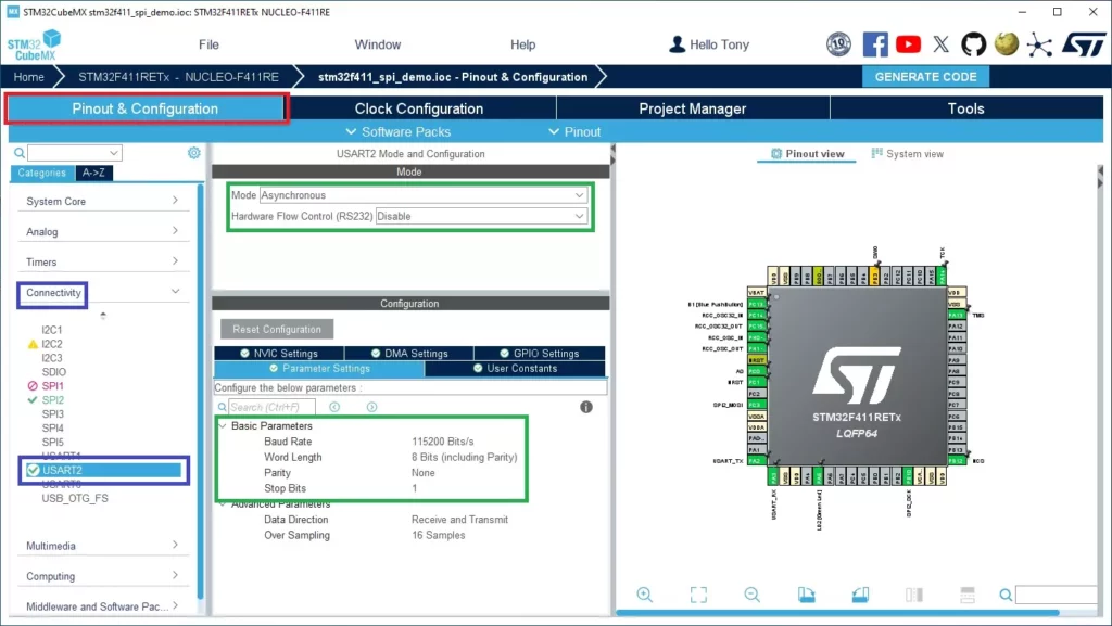
Configuring USART2 is straight forward as the default parameters require no changes. See the image below for configuration. Though not used in this project, the USART is included for debugging.
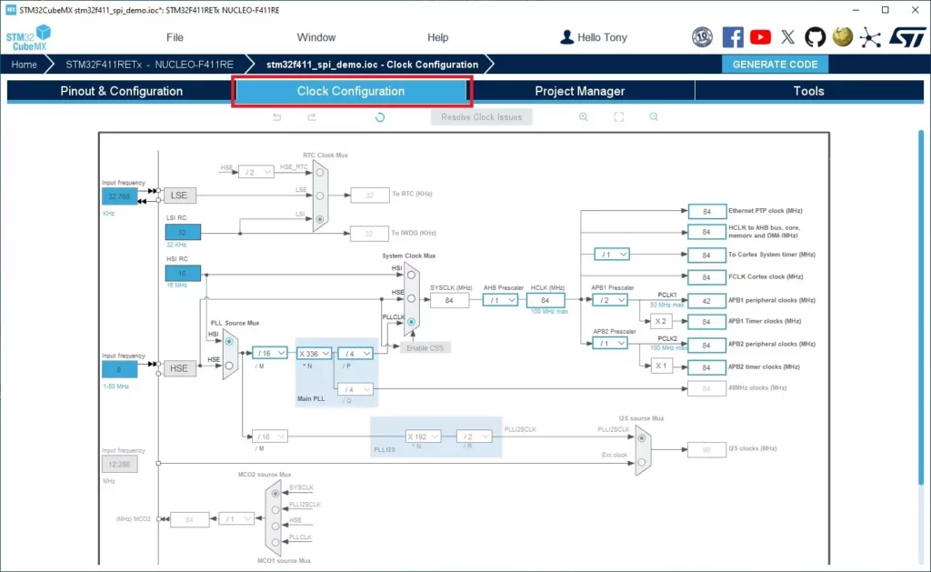
Finally, the clock will be configured. The default settings for the clock peripheral are good for this application and will not be changed from the default values. The image below shows the clock configuration.
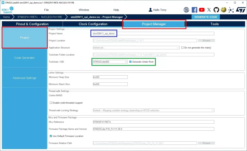
Project Management
The next section to configure is the “Project Manager” tab. Under the tab will be 3 sections on the left-hand side of the window. Make sure “Project” is selected. Here is where the project settings will be entered. Provide a name for the project and then select the toolchain from the drop-down menu. Keep “Generate Under Root” box checked.
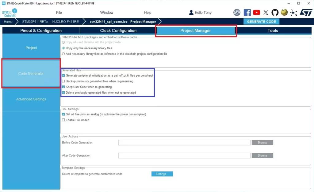
In the next section “Code Generation”, make sure the radio button “Copy only the necessary files” is selected and that the check boxes “Generate peripheral code initialization as a pair of ‘.c/.h’ files”, “Keep User Code when re-generation”, and “Delete previous generated files when not re-generated”.
The final step in setting up the project is to click on “GENERATE CODE”.
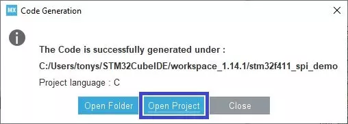
Once the code generation is completed, the following dialog box will allow the project to be opened within the STM32CubeIDE.
STM32CubeIDE
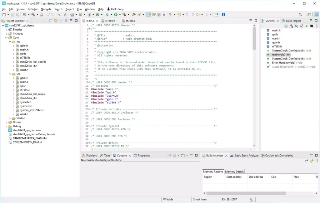
Now that the project setup with STM32CubeMX is complete, the project can be opened in the IDE. There will be several pre-generated files including header and source files for the different peripherals. Modification will be made to the main.c file along with the addition of st7565.h and st7565.c files.
Add Files
Two files need to be added to the project: st7565.h and st7565.c. Place these files in the Inc and Src folders of the project. Then right click the top-level project file in Project Explorer and select refresh to update the project with the new files. Contact Focus LCDs to obtain the individual files or the complete set of project files.
Currently, the st7565.h file contains the command definition for the ST7565 controller chip along with display specific definitions. Function prototypes for interfacing with the SPI bus, for controlling the display features, and the graphic functions are all included in this file. The st7565.c file contains the definitions of the functions used to send commands and data over the SPI bus and controlling the display. The graphic functions have not had their code added at this time but might be included in a future release.
Modify the Code
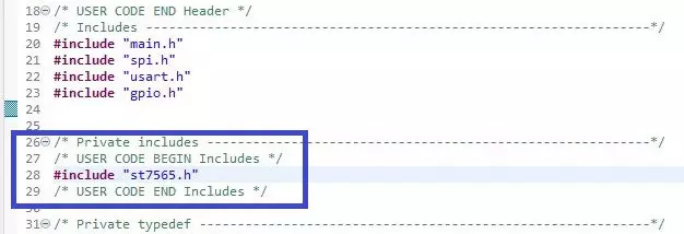
In main.c a few modifications are needed to complete the application. The #include “st7565.h” needs to be added to the code. After the generated includes, the previous line gets placed between the USER CODE BEGIN/END includes comments as shown below.
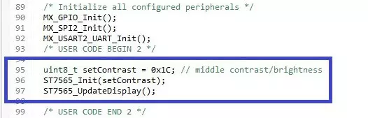
The final modification is to add the code for initializing the display and updating what is displayed on the screen.
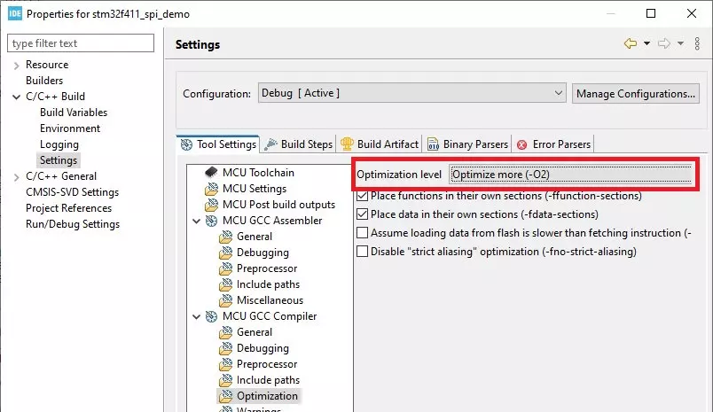
Change the Optimization Settings
The next step in creating the firmware is setting the optimization level. The typical setting is ‘-O2’ for a good compromise between execution speed and code size. If left at ‘-O0’, there would be no optimization for execution speed and code size. Depending on whether debugging the application code or releasing the application code the optimization settings can be adjusted. In this application, it will be changed to ‘-O2’.
First, in Project Explorer right click on the project and select properties.
In the pop-up window, select C/C++ Build->Settings. Then in the Tool Settings tab on the right, select Optimization and set the Optimization level to -O2.
The final step is to build the project. This step ensures that there are no missing dependencies. If there are any errors or warnings, resolve those issues before continuing with the firmware project.
In the Appendix, additional information is included to support expansion to graphical application.
The following images show a simplified, monochrome Focus LCDs logo on the graphic LCD with the various backlight colors.
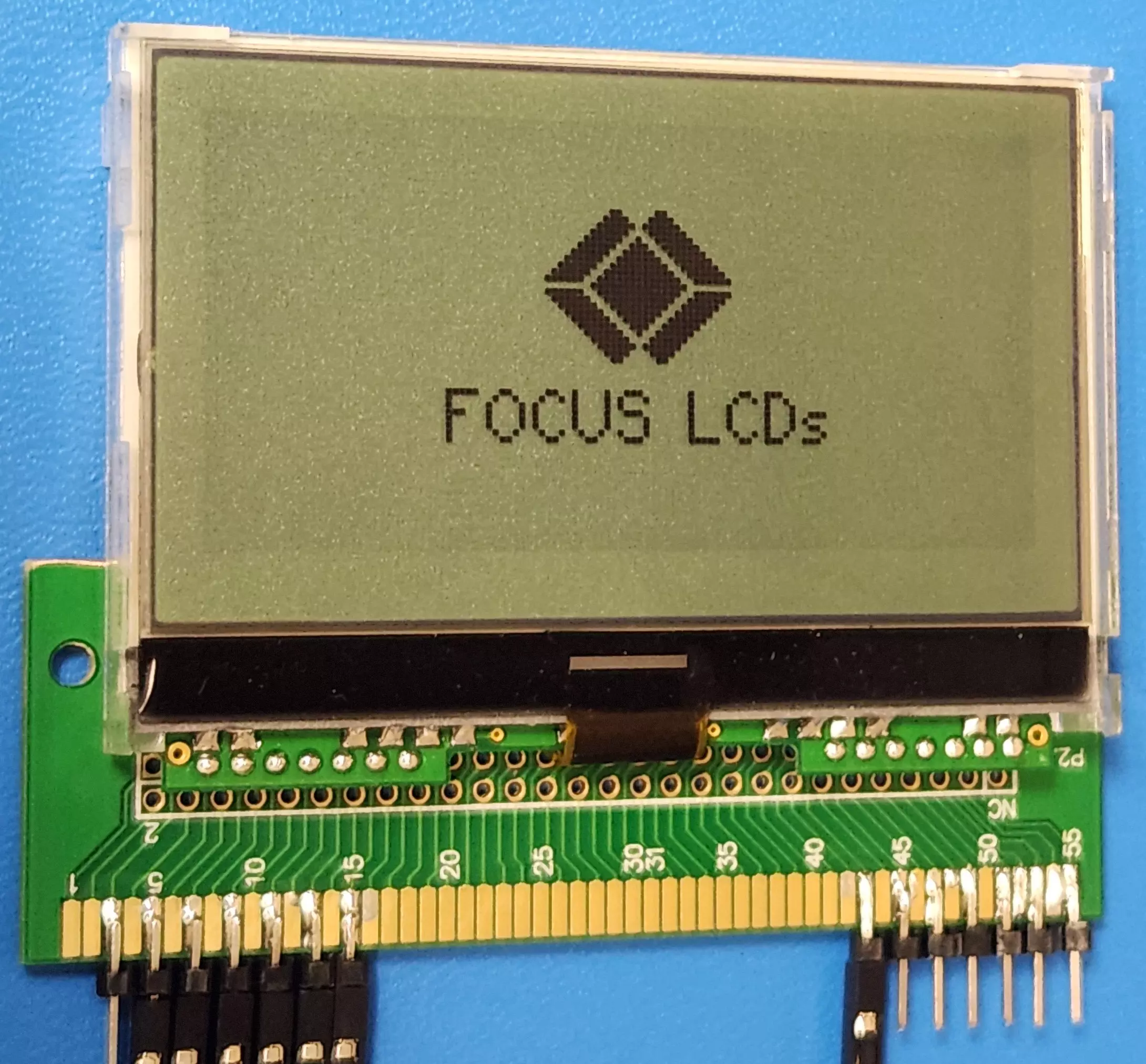
no Backlight
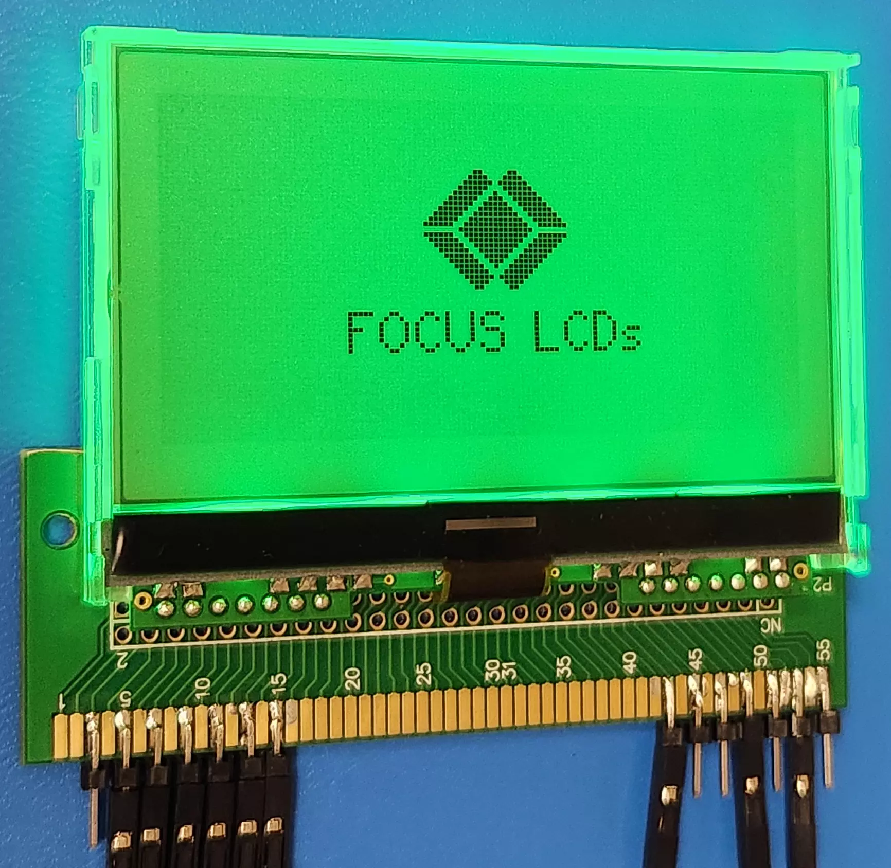
Green Backlight
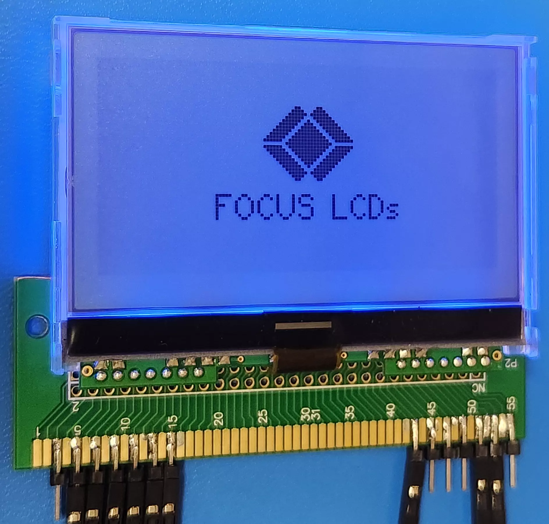
Blue Backlight
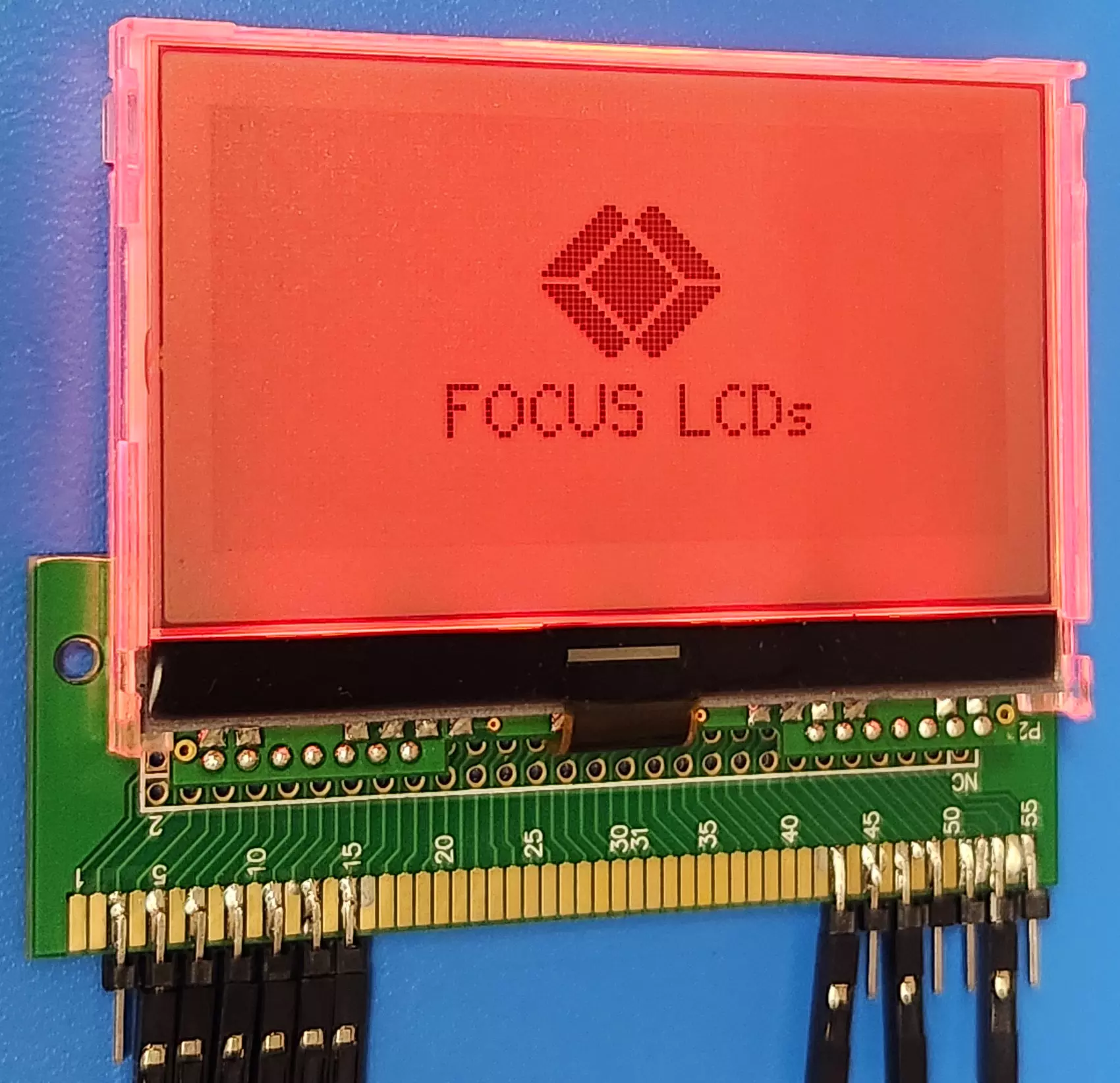
Red Backlight
Summary
In this application note, it was shown how to connect and drive a graphic LCD. This application can be used as a reference to drive any of the Focus LCDs graphic display that use the ST7565 controller chip. An STM32 Nucleo board was used as the development board to drive the display. Wiring the display to the development board required a small piece of prototyping board for the connections. The tools provided by ST Microelectronics aided in the development of the application firmware by generating all the low-level peripheral code.
Appendix
Turning the code into a larger graphical application requires several modifications. Making the code modular is the priority by splitting out the functions into 3 levels. The code presented in this application note was just to show how to set up a development board, connect to the display, and drive an image to the display.
The lowest level of code above the SPI interface code would be the ST7565 header and source files. The header file should just contain the command (and associated data) defines along with the external SPI handle and function prototypes. The source file should only contain the command and data functions. This would be the only level that interfaces with the SPI peripheral. By setting up the code this way allows the ST7565 files to be used with different graphic LCDs that use the ST7565 controller chip.
The second level should be header and source files specific to the graphic display. In this case, a G126FLGFGS164T33XAR graphic LCD. In the header file, there should be the specific definitions for the display (i.e. the resolution) and the function prototypes. The only functions that should be at this level in the source file are the display initialization, brightness setting, a way to clear the display, and a function that either takes a single data or a data array to write to the screen. These functions will have specific code for the display used in the project.
The final level will be the graphics code. Functions that provide the basic graphic features of drawing a pixel, line, rectangle, circle, and bitmap should be placed at this level. This is the level that should have the frame buffer where all the drawing functions write their data. If the lower-level functions that this layer accesses are generically named or function pointers are used, then the graphic display can be replaced easily with another graphic display.
Building the display and graphics code in this way allows the easy replacement of the LCD with another that uses the same controller chip.
LCD Handling Precautions
- Do not store the graphic LCD module in direct sunlight, best stored in a dark place.
- Do not leave it exposed to high temperature and high humidity for a long period of time.
- Recommended temperature range is 0 to 35 °C, relative humidity should be less than 70%.
- Stored modules away from condensation as formation of dewdrops may cause an abnormal operation or failure of the module.
- Protect the module from static discharge.
- Do not press or scratch the surface and protect it from physical shock or any force.
Disclaimer
Buyers and others who are developing systems that incorporate FocusLCDs products (collectively, “Designers”) understand and agree that Designers remain responsible for using their independent analysis, evaluation, and judgment in designing their applications and that Designers have full and exclusive responsibility to assure the safety of Designers’ applications and compliance of their applications (and of all FocusLCDs products used in or for Designers’ applications) with all applicable regulations, laws, and other applicable requirements.
Designer represents that, with respect to their applications, Designer has all the necessary expertise to create and implement safeguards that:
(1) anticipate dangerous consequences of failures
(2) monitor failures and their consequences, and
(3) lessen the likelihood of failures that might cause harm and take appropriate actions.
The designer agrees that prior to using or distributing any applications that include FocusLCDs products, the Designer will thoroughly test such applications and the functionality of such FocusLCDs products as used in such applications.